Subtract and Branch if Negative
I got pretty bored over winter break, and decided I needed a project to keep me busy until class started. Well, there was one thing that I've been wanting to do for a long time. I have wanted to build a simple computer out of 7400 series logic chips. I only had about a week for the whole project, so the design had to be pretty spartan. I also wanted to use chips that I had on hand, though that didn't last for too long.
After thinking up a few different ideas, I finally remembered another project that I've been wanting to do: build a Subtract and Branch if Negative computer. That is, a computer whose only instruction is to subtract two numbers, store the result, and branch to an alternative memory location if the result is negative. This is very much like SBN on wikipedia.
If you don't care to look at the Wikipedia page, the subtract and branch if negative instruction turns out to be the only instruction you need to build a turing-complete computer. That is, this one instruction, given enough time and memory, can compute anything that a regular computer can. Of course, it's slow, inefficient, and a pain to program.
 So I went about designing a simple microcomputer based on this instruction. First step, I needed to decide on some basic specifications for the processor:
Data Width: 8-Bits
Address Space: 16-Bits
Instruction Set: Subtract and Branch if Negative
After that, I could rough out a block diagram of the dataflow. Using the dataflow as a guide, I figured out what chips I could use in what blocks, how many I would need and how they connect to each other.
The dataflow was the easy part. More difficult is designing the control logic, which was going to be especially complicated because of the 8 and 16 bit busses. This is because it now requires two cycles to read in the address of an operand, and another cycle to read in the value of the operand. This needs to be done once for both operands, and then again when we need to load the new PC value if the instruction takes the branch.
The control sequence for the processor goes something like this:
- Load MAR.H; PC++
- Load MAR.L; PC++
- Load B
- Load MAR.H; PC++
- Load MAR.L; PC++
- Load A
- Store ALU Result; PC++
- Load PC.L
- If (ALU Result is negative) {Load PC}
So we have the control and the dataflow...what else? Input and output. There needs to be a way to load programs onto the device, and then a method of interacting with the running program.
I had initially thought about using a series of switches for loading programs into RAM. That was going to be incredibly tedious and time consuming, so I scratched that. Instead, I did some research on the Parallel port, and found it to be the perfect solution. It's easy to interface, easy to program and completely automated. This only required a few extra chips to interface the parallel port to the system bus on the microcomputer. Basically, it needs to be able to take control of the bus when it needs to program, and relinquish control when it's done.
 Last bit of hardware, the human machine interface. I have to admit, it's pretty craptacular on this microcomputer. An 8-bit dipswitch and an 8-LED bargraph are all the I/O you get. However, this fits in with the overall strategy of making somewhat rediculous design decisions. There is however, at least one neat trick that can be done to expand the output capabilities.
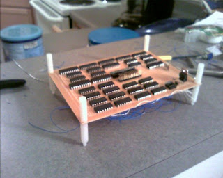
The fabrication of this computer is another story. I had hoped I would be able to build it on a printed circuit board, that would have been wonderful. However, I had too many chips for the free version of Eagle CAD I had. Simply would not fit on the board. So I decided to use a pre-drilled perferated board with solder pads. Good enough, but wiring ended up taking most of the week. Luckily for you, you don't have to wait to see the finished product. The final stage of the microcomputer has two boards. The bottom board has the processor, memory, power supply and clock generator. The top board holds the batteries, has some blinky lights, dip switch and some simple address decode logic for memory-mapped IO.
To wire up all the parts, I used a lot of wire-wrap wire, solder and a wire-wrap tool. The leads
 on the parts were very short, so wire-wrapping was a real pain, but it seemed to be the best way to get the leads into place for soldering. It was slow going and took about four very full days to finish. On top of that, I had to test and debug different parts as I finished them. It can make you pretty nervous when you have to desolder several connections on one IC to make a fix.
If I do another 7400 series-based microcomputer, I will get a proper wire-wrap board.
Now that the darn thing is built, what to do? The work's not done yet. After building and debugging it, I still needed to be able to write, assemble and load programs. I needed to write an assembler and program loader.
The program loader actually turned out to be the easiest part of the whole project. Programming the parallel port on Linux was much easier than I expected. In fact, the loader program only had one bug in it the first time I tried it. Made the fix, tried it again, worked!
Now that I could load any data I wanted into the microcomputer's memory, I needed an easier way to program it. This meant developing a simple two-pass assembler. On top of that, I wanted it to have some built-in pseudo operations, so I could program and still keep my sanity. Programming this device with only using the low-level subtract and branch if negative instruction is not my cup of tea.
Eventually I hacked out a simple assembler that fit the bill. The assembly code looks like this:
sub i, imm(-10)
loop:
dec i
bltz i, loop
This little snippet is a simple loop. It subtracts -10 from i (which it assumes to be 0), setting up the number of iterations. Each iteration it decrements the loop index, and continues to loop as long as "i" is greater than or equal to zero.
Each instruction in that snippet is a pseudo-operation that is converted into SBN instructions by the assembler. Furthermore, each of those pseudo-ops can be converted into exactly one SBN instruction.
The "imm(-10)" bit of code allows me to operate with immediate values in my code.
 All it does is return the address of the value"-10" on the constant table. These keeps me from having to allocate a memory location for each constant I use in my code.
I now have everything I need to write a demo program. I wanted the microcomputer to do something unexpected. Something you wouldn't think it would be able to do. I think the most limiting part of it is it's input and output. I decided the demo would be an output-only program. This leaves me with eight blinky lights to do something cool with.
So, the most unexpected thing to do, would be to project an image with those eight lights. That's my thought anyways. I was set on displaying a smiley face using just those lights. How, you might ask, can that be done? Using persistance of vision.
If you've ever looked at a flashlight in the dark, you've probably noticed that it seems to leave a trail when you look at it. If you spin it in a circle fast enough, you might see a circle of light,
 neato. The idea behind displaying a smiley face on the eight lights is the same. If I move the lights, or use a mirror to move them, your eyes will see a trail marking where that light has been in your field of vision. If we setup a regular motion of a mirror, and display one line of the image at a time, we can display an entire 2D image using one line of eight lights.
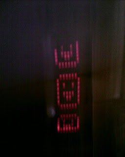
So that's what I did. The program outputs one line of the desired image, blanks the lights for a split second, the next line is lit up, and so on. I took a picture of the effect with my camera. I don't have any mirrors yet, so I just panned the camera across the lights in the dark, it worked out really well. To show other people, I can just shake the lights up and down. Eventually, I would like to get a small mirror, motor and switch for synchronization. That seems a bit safer than shaking the fragile computer.
In the end what I got is an 8-Bit computer with one instruction, 32 KB of RAM and a clock speed of 250KHz. Though it takes nine cycles to execute one instruction, so in reality, it's executing about 28,000 instructions per second.
